Current Transformer Schematic Circuit Diagram
Transformer spaco Ideal transformer in detail with schematics and equations Current transformer circuit equivalent transformers power ct burden derivation
Transformer Ratios of Single-Phase Transformers | Electrical A2Z
Control transformer wiring diagram power motor electrical diagrams circuits starter 120v Current transformer and potential transformer, circuit diagram, working What is current transformer (ct)?
Transformer ratios of single-phase transformers
Winding current transformers in low voltageWiring diagram for transformer Transformer ct electricalworkbookWiring of control power transformer for motor control circuits.
Current transformers voltage core low turns winding inside cross primary section ag mbs measuring higher due required numberEquivalent circuit of transformer referred to primary and secondary 14+ current transformer circuit diagramTransformer diagram wiring current wire tranformer circuit.
![Current Transformer And Potential Transformer, Circuit Diagram, Working](https://i2.wp.com/cselectricalandelectronics.com/wp-content/uploads/2020/08/Current-Transformer-768x432.jpg)
The essentials of current transformers in power circuits (theory and
Transformer phase single electrical load schematic transformers diagram figure ac connected supply symbols ratios its turns show standard power usingEquivalent circuit of transformer referred to primary and secondary Ideal equations lossesTransformer current diagram circuit potential loaded electrical transformers typical connected standard.
Transformer current circuit ct diagram secondary types phasor construction primary definition circuitglobe14+ current transformer circuit diagram Transformer equivalent referred parameters determination winding electricalacademiaWhat is current transformer (ct)? definition, construction, phasor.
![Ideal Transformer in detail with Schematics and equations](https://i2.wp.com/www.electricalclassroom.com/wp-content/uploads/2020/09/Ideal-transformer.png)
14+ schematic diagram of transformer
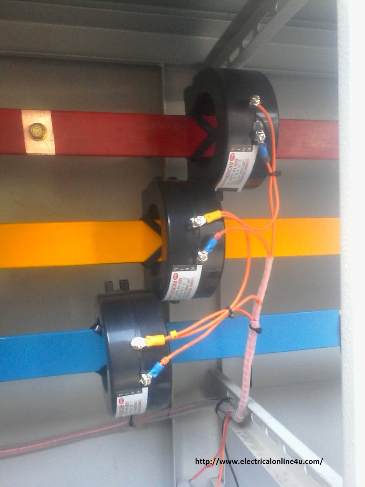
Transformer circuit equivalent phasor primary secondary side referred parameters form voltage electrical resistance determination fig ratio electricalacademiaElectrical topics: circuit diagram of loaded current transformer and Current transformer wiring installation ct diagram phase coil three power supply meter connect electrical coils amp soCurrent transformer installation for three phase power supply- ct coil.
.
![Equivalent Circuit of Transformer Referred to Primary and Secondary](https://i2.wp.com/electricalacademia.com/wp-content/uploads/2017/10/Actual-Transformer.gif)
![The Essentials Of Current Transformers In Power Circuits (Theory and](https://i2.wp.com/electrical-engineering-portal.com/wp-content/uploads/2018/12/equivalent-circuit-current-transformer-derivations.gif)
![Current Transformer Installation For Three Phase Power Supply- CT Coil](https://4.bp.blogspot.com/-pWoagPR_ALs/Vthb4HLI9fI/AAAAAAAAAhg/u396SGzUJRo/s1600/current%2Btransformer%2Binstillation%2Bfor%2Bthree%2Bphase%2Bwiring.jpg)
![Wiring of control power transformer for motor control circuits | EEP](https://i2.wp.com/electrical-engineering-portal.com/wp-content/uploads/2016/10/control-transformer-wiring-diagram.png)
![Transformer Ratios of Single-Phase Transformers | Electrical A2Z](https://i2.wp.com/electricala2z.com/wp-content/uploads/2018/01/Figure-4.-Diagram-using-standard-electrical-symbols-to-show-the-AC-supply-a-single-phase-transformer-and-its-connected-load-in-an-electrical-schematic.png)
![14+ Current Transformer Circuit Diagram | Robhosking Diagram](https://i2.wp.com/spaco.org/electronics/CTSensorSchematicEagleSmRev.jpg)
![Winding Current Transformers in Low Voltage | MBS AG -EN-](https://i2.wp.com/mbs-ag.com/wp-content/uploads/2020/11/Bild_3-Wickelstromwandler_EN.jpg)
![What is Current Transformer (CT)? Definition, Construction, Phasor](https://i2.wp.com/circuitglobe.com/wp-content/uploads/2016/11/current-transformer-circuit.jpg)
![electrical topics: Circuit Diagram of Loaded Current Transformer and](https://4.bp.blogspot.com/-slFuUDBHe2s/VLURQTIL0WI/AAAAAAAAQJ8/8bFNWXyKlsY/s1600/circuit-diagram-of-loaded-current-transformer-and-potential-transformer.png)
![Equivalent Circuit of Transformer Referred to Primary and Secondary](https://i2.wp.com/electricalacademia.com/wp-content/uploads/2017/10/Transformer-Equivalent-Circuit-in-Phasor-Form-3.gif)