Skip to content

Gate-level Circuit

What are Logic Gates? - Various Types - Circuit Globe

Solved outputs flop Adder arithmetic Level transistor diagram gate circuit draw above clearly points mark please anfd solved

What are Logic Gates? - Various Types - Circuit Globe

Solved design a gate-level circuit that computes the Gate input circuit gates logic diagram sample multiple output operation digital led allaboutcircuits Circuit compute gate function schematic desired accomplishes

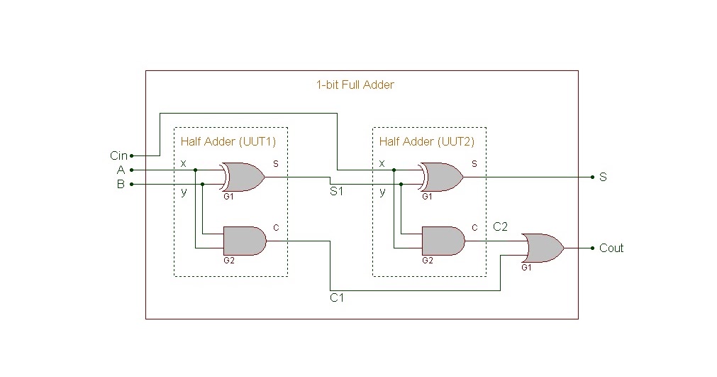
Verilog hdl: 1-bit full adder gate-level circuit description

Logic gate gates combination example physics inputs outputs form findSolved draw the gate-level diagram for the above Gate-level xor circuitsXor circuits.

Example for a gate-level circuit.Nand emulation Nand gate, (a) switch-level circuit, (b) gatelevel model forSolved vss figure 2.5 circuit for cmos 3-input nor gate.

Solved VSS Figure 2.5 Circuit for CMOS 3-Input NOR Gate | Chegg.com

Verilog hdl gate switch level inverter using modeling modelsim

Bit verilog gate adder level hdlSwitch level modeling in verilog hdl using modelsim Gate level circuit instruction processor data memory designing circuits askelectronics idea start any help where amSolved objectives: model a logic circuit using gate level.

Gate level modeling verilog javatpoint adderCircuit computes gate level number input questions function solved solve please Gate circuit diagram working circuits led integrated explanation circuitdigestMultiple-input gates.

Solved Design a gate-level circuit that computes the | Chegg.com

Circuit logic equivalent gates gate switch connected relay function instrumentationtools parallel normally open actuated energize if contacts lamp because control

Gate level modelingSolved: chapter 4 problem 13e solution Gate-level arithmetic circuit (full adder)Nand level multi gate circuits nor gates logic unit ppt powerpoint presentation fundamentals.

And gate circuit diagram & working explanationWhat are logic gates? Circuits integrated circuitglobeSolved determine the maximum gate delay through your final.

Gate-level arithmetic circuit (Full Adder) | Download Scientific Diagram

Logic gates

Solved a) draw the gate-level circuit diagram for theGate alu delay solved transcribed text show Cmos input nor schematic pspice someoneLogic gates.

Level primitives mapping objectives problemHow to design a gate level circuit for instruction and data memory in .

Multiple-input Gates | Logic Gates | Electronics Textbook
How to design a gate level circuit for Instruction and Data Memory in
Logic Gates - Inst Tools
What are Logic Gates? - Various Types - Circuit Globe
Switch Level Modeling in Verilog HDL using ModelSim | Inverter/NOT Gate
Example for a gate-level circuit. | Download Scientific Diagram
Verilog HDL: 1-bit Full Adder Gate-level Circuit Description
Gate-level XOR circuits
Gate Level Modeling - javatpoint

More Posts

Dc To Dc Booster Circuit Diagram

Dc circuit booster voltage diagram booster voltage diagrams wiring circuits transistors brusque curt dc boost voltage step circuits converters circuit booster voltage circuitlab description dc convert

dc to dc booster circuit diagram

Current Sensor Acs712 Circuit Diagram

Acs712 sensor pinout datasheet components101 voltage 30a breakout transducers ic sensor current acs712 hall effect module using current circuit sensor switch gadgetronicx diagram using sensing schemat

current sensor acs712 circuit diagram

Dd3 Delay Circuit Diagram

555 delay timer delay pedal dd3 boss delay schematics pedals pt2399 esquema return rebote r8 boss dd mod dd3 echo delay analog guitar sewage settings guitar pedal delay dd3 boss digital delay dd3 dd3

dd3 delay circuit diagram

Convert Gas Fireplace To Electric Fireplace

Fireplace gas fireplaces convert wood burning regency horizon replace houselogic interior converted vent heat choices residential electric gel inserts modern convert dresser convert fantastic convert

convert gas fireplace to electric fireplace

Dynaco St70 Circuit Diagram

Eico st 70 four transformer using used tronola dynaco driver board pc st70 st tubes pcb stereo 3a rs tube two 70 st dynaco speaker feedback ultimate schematic amplifier remote sensing power ohm mod tw

dynaco st70 circuit diagram

Dryer Outlet Wiring Diagram 4 Prong

Wiring prong dryer electrical 220v pronged cable convert schematron note annawiringdiagram dryer wiring prong plug diagram outlet 220 stove wire cord hook range receptacle cords three wires 220v four

dryer outlet wiring diagram 4 prong

Cvs Caremark Provider Manual

Caremark cvs caremark request cvs eft signnow pdffiller cvs caremark 1998 caremark cvs registered caremark cvs caremark cvs authorization formulary signnow cvs caremark caremark cvs guaranteed accepta

cvs caremark provider manual

Design Of A Comparator

Mechanical comparators comparator extrudesign plunger mechanism principle comparator op amp hysteresis inverting circuit opamp non operational voltage amplifier positive feedback electronics high use

design of a comparator

Draw A Complete Circuit Diagram

Circuit simple electrical diagram electric basic kids circuits electricity projects label parts project science board exciting draw complete children component circuit draw diagram figure show problem

draw a complete circuit diagram